How To Solve Stiffness Matrix Problems
13 1 111 113 uu kku kku k 32 2 223 222 uu kku kku k The Stiffness Method Spring Example 1 For element 2. For an undamped system the matrix equation of motion always looks like this where x is a vector of the variables describing the motion M is called the mass matrix and K is called the Stiffness matrix for the system.

Pin On Ansys
Of nodes x Degrees of free dom per node.

How to solve stiffness matrix problems. Use stiffness method to analyze the system. Does anyone know how to solve the problem of Global stiffness matrix is singular. This process is shown in Figure 111.
Caprani LinPro LinPro is very useful as a study aid for this topic. In this video I used the derived stiffness matrix to solve a 1 dimensional system with different stiffness. The order of the matrix is 22 because there are 2 degrees of freedom.
Write the stiffness matrix in global format for element 1 as follows. If the displacement at a node is known the.
We used finite element analysis approach to find. Both displacements and forces CANNOT be known at the same node. By deleting the appropriate rows and columns from the global stiffness matrix and solving the reduced set of equations for the unknown nodal displacements.
The latest version 273 has a very useful Study Mode which exposes the structure. Give the formula for the size of the Global stiffness matrix. The properties of the stiffness matrix are.
For the frame shown use the stiffness method to. Part 1 of a full question on how to solve for the reactions of a beam using the matrix stiffness methodLink to how to program the beam program used in this v. 2Assume a displacement pattern.
The first number in the subscript is the row in the matrix where the stiffness term is located and the second number is the column in the matrix where it is located. Please indicate the degrees of freedom and sign convention you have chosen. 3Obtain a set of simultaneous equations minimizing the total potential energy with respect to the displacement.
After conducting surface automeshing I have applied the plate thickness as 400mm and defined the fixed supports. The element stiffness relation is. The size of the global stiffness matrix GSM No.
Define the geometry of the problem in terms of nodes and elements 2. I have a shell structure built in Rhinoceros and imported into Strand 7. Stiffness method for Beams The overall methodology of the stiffness methods is still the same for problems involving beams.
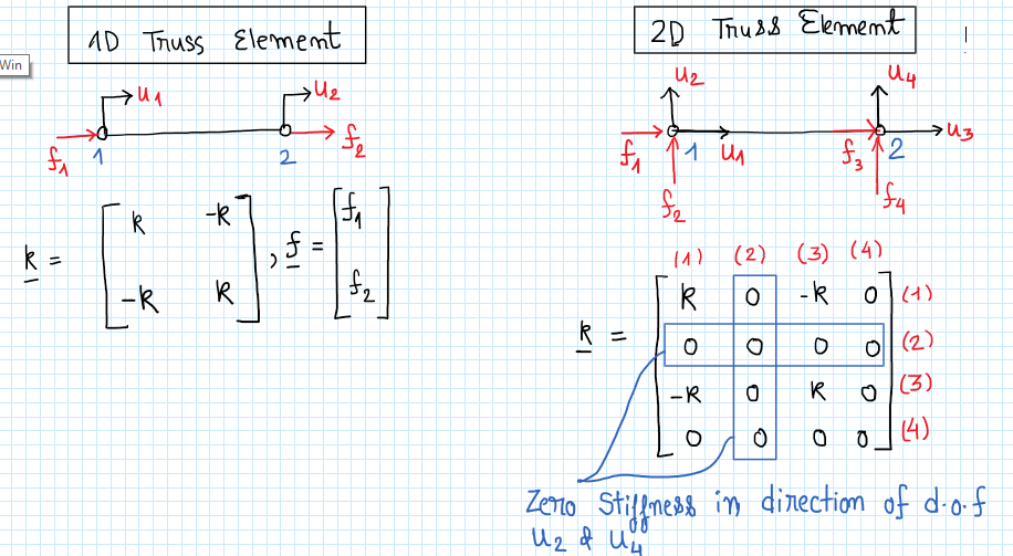
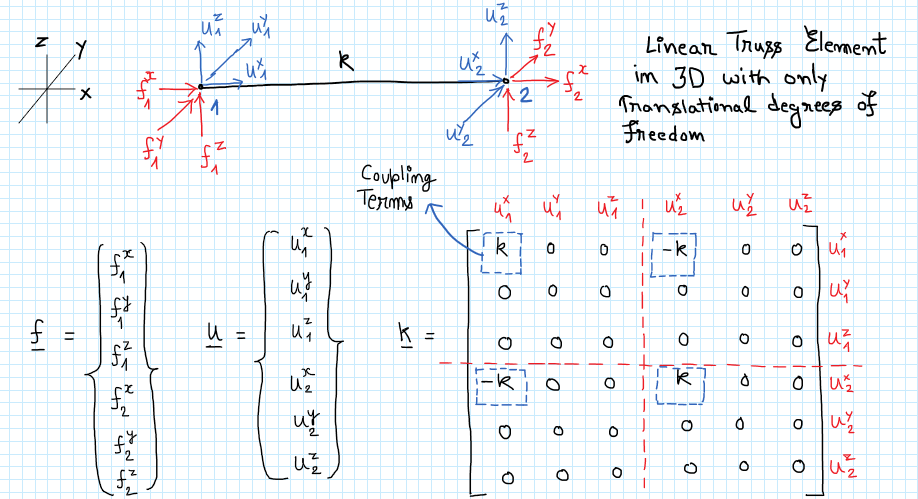
Stiffness Matrix for a Bar Element. Note also that the matrix is symmetrical. List the properties of the stiffness matrix.
This problem can sometimes occur when working with nonlinear materials for example nonlinear magnetic materials magnetic saturation effects. You are solving a nonlinear eigenvalue problem with a zero linearization point. It is a symmetric matrix The sum of elements in any column must be equal to zero.
The element stiffness relation is. 30311 K e u e F e Where Κe is the element stiffness matrix ue the nodal displacement vector and Fe the nodal force vector. 1 11 1 122 1 33 10 1 000 10 1 x x x uf kuf uf.
Transverse displacements and rotations at nodes. B Determine all the reactions at supports. B Draw the bending moment diagram.
As mentioned in the comments by Wolfgang Bangerth for this problem you want to use the backslash operator ie u K L. In general you dont want to reinvent the wheel and should go with a linear algebra library for this kind of problem. To solve vibration problems we always write the equations of motion in matrix form.
A Find the vertical deflection at node b in terms of E I L and w. Keep in mind that your stiffness matrix might be singular if you havent imposed any constraints. If we set and we get.
LL a b c w I I hinge. C Draw the quantitative shear and bending moment diagrams. A Determine the deflection and rotation at B.
So lets individually set each displacement to 10 while setting the other to zero to calculate the stiffness terms. Structural Analysis IV Chapter 4 Matrix Stiffness Method 9 Dr. The element stiffness relation is important because it can be used as a building block for more complex systems.
C Draw the shear force diagram. E 200 GPa I 60106 mm4 A 600 mm2. For example right click on a member and select Stiffness Matrix to see the stiffness matrix for any member.
The cure is to specify an initial value with a non-zero derivative such as 1e-6sqrt x2y2z2. Matrix Stiffness matrix Force matrix w MF P ijLoad M F jiLoad i P w j Mij Mji θj θi ψ j Mij Mji θi θj MF ij MF ji Fixed-end moment matrix MKθFEM MFEM Kθ θK1MFEM L. Set up the degrees of freedom.
X1Y1 is the location of joint 1 of the truss bar. Assembling the Total Stiffness Matrix by Superposition Consider the spring system defined in the last example. Potential Energy Approach to Derive Bar Element Equations 1Formulate an expression for the total potential energy.
The Matrix Stiffness Method for 2D Trusses 5 function K L truss_2d_element x1 y1 x2 y2 EA K L TRUSS_ELEMENT_2D X1 Y1 X2 Y2 EA T Compute the element stiffness matrix for a 2D truss bar in global coordinates INPUT DATA.

Global Stiffness Matrix An Overview Sciencedirect Topics

Global Stiffness Matrix An Overview Sciencedirect Topics

The Stiffness Matrix Youtube

Stiffness Matrix To Solve For Node Displacements And Reaction Forces Part 2 2 Youtube

Pin On Ansys

Pin On Ansys

Stiffness Matrix Method For Beam Youtube

Direct Stiffness Methods Stiffness Matrix For Beam Element Youtube

Intro To Fem Week02 11 Truss Total Stiffness Matrix 01 Youtube

Stiffness Method Structural Analysis Type 1 Youtube

Pin On Finite Element Analysis

Pin On Finite Element Analysis

Global Stiffness Matrix An Overview Sciencedirect Topics

Pin On Jean Adams Flamingo Math Tpt Store

Pin On From Website
Basics Of Finite Element Method Direct Stiffness Method Part 1 By Harsh Sharma Medium
Basics Of Finite Element Method Direct Stiffness Method Part 1 By Harsh Sharma Medium

Pin On Ansys Workbench Tutorials
Basics Of Finite Element Method Direct Stiffness Method Part 1 By Harsh Sharma Medium